The most advanced sealing material and the most precise geometric design are rendered useless by one common factor: poor seal installation. Industry statistics suggest that a significant percentage of premature seal failures occur not because the seal was defective, but because it was damaged during assembly or improperly maintained. Effective maintenance techniques and proper handling during seal replacement are essential to achieving the designed lifespan of hydraulic seals and other industrial components.
Part 1: Storage and Shelf Life Management
Proper seal maintenance techniques begin before the part is even unpacked. Elastomers are sensitive to environmental factors. Improper storage leads to “shelf aging,” where the seal cracks before it sees service.
The Rules of Rubber Storage
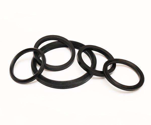
Standard O-Ring Rubber Seals (NBR, FKM, HNBR, EPDM) should be stored in cool, dark environments. UV light and ozone (from electric motors) attack the molecular bonds of rubber.
- Temperature: Keep below 25°C. Heat accelerates curing.
- Relaxation: Do not hang O-rings on hooks. This causes gravity-induced stretching. Store them flat.
- Chemical Isolation: Keep away from solvents. For chemical plants, keeping a stock of FEP Encapsulated O-Rings is vital, as their Teflon jacket protects the core from atmospheric degradation.
For proper seal replacement and installation techniques, refer to authoritative standards such as ASTM Standards and ISO 3601 O-Ring Guidelines to ensure optimal performance.
PTFE and Metal Storage
Materials like PTFE and metal are indefinitely shelf-stable but physically fragile. PTFE Gaskets and Hollow Metal O-Rings must be protected from crushing weights. A dent in a metal seal renders it useless, affecting both hydraulic seals and rotary shaft seals.
Part 2: Hydraulic Cylinder Assembly Best Practices
Replacing hydraulic seals is a precise operation. Scratches on the seal during seal installation are the #1 cause of “zero-hour” leaks.
Preparation: Cleanliness and Chamfers
Before installing a UNS Piston Rod Seal, inspect the hardware. Are there sharp burrs? A lead-in chamfer is mandatory. If the rod has no chamfer, the seal lip will be sliced upon insertion.
Piston Seal Installation
Multi-piece seals like the SPGW Piston Seal require a specific sequence:
- Install the energizer (rubber O-ring) first.
- Install the back-up rings.
- Install the PTFE face. Note: PTFE faces often need to be expanded to fit over the piston and then “resized” (compressed) back to the correct diameter using a calibration sleeve.
For simpler, one-piece designs like the SPG Piston Seal, ensure the seal is not twisted in the groove.
Rod Seal Techniques for Successful Seal Replacement
Rod seals are difficult because they are installed into a “blind” internal groove.
- Fold into Kidney Shape: Flexible U-cups like the IDI rod seal can be folded into a kidney shape to fit into the gland.
- Do Not Use Screwdrivers: Never use sharp metal tools to push the seals. Use plastic assembly tools.
- Compact Seals: The S8 rod seal is rigid. Heating it in warm oil (approx. 60°C) can make it pliable enough to install without damage.
Guidance and Wiping
Never forget the wear rings. phenolic resin with fabric wear rings should be cut with a specific gap (scarf cut) to allow for thermal expansion. Finally, press the DKBI dust seal carefully into the housing, ensuring the metal case does not deform.
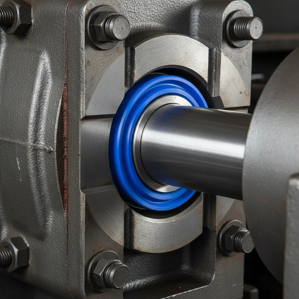
Part 3: Rotary Shaft Seal Installation
Installing a crank seal or standard oil seal requires attention to the shaft surface and direction.
Orientation Matters
The primary lip of the TC oil seal must face the fluid being sealed. If installed backward, it will pump oil out of the machine.
- Protect the Lip: If the shaft has splines or keyways, cover them with tape or a mounting sleeve. Sliding a seal over sharp splines will ruin the sealing edge immediately.
- Lubrication: Always grease the lip of the seal and the shaft before installation. Running a dry seal on startup will burn the rubber.
Advanced Rotary Install
For PTFE oil seals with stainless steel cases, the lip is stiff. It requires a concentric installation tool to press it evenly into the bore. Do not hammer it directly.
When using VA rings or VL rings, ensure the shaft is clean. The V-Ring relies on friction to grip the shaft and rotate with it. If the shaft is oily, the V-Ring might slip.
Part 4: Gland Packing and Pump Maintenance
Replacing gland packing in pumps is a routine maintenance task, but often done incorrectly.
The Correct Procedure
Do not simply wrap a continuous rope around the shaft.
- Cut Individual Rings: Whether using aramid fiber gland packing or high pressure graphite gland packing, cut rings to the exact circumference of the shaft.
- Stagger the Joints: Install rings one by one. Stagger the cut joints by 90 degrees (like clock positions 12, 3, 6, 9). This prevents a direct leak path.
- Compression: Tighten the gland follower just enough to seat the rings, then back off. Start the pump and tighten slowly until leakage is a controlled drip (required for cooling). Overtightening burns the packing.
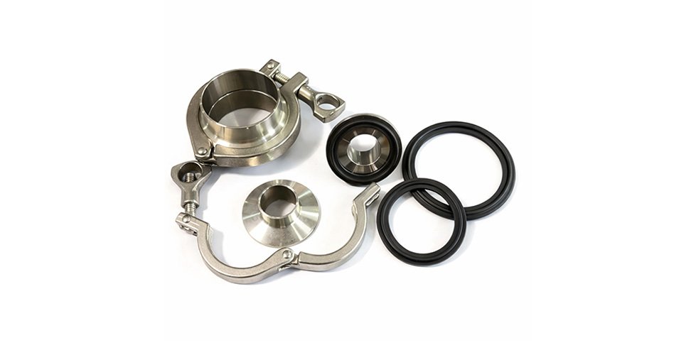
Part 5: Static and Flange Sealing
Leaking flanges are a safety hazard. Proper torque sequence is key.
Gasket Selection and Torque
Ensure the Seal for Gasket matches the flange face.
- Paper Gaskets: For Red Steel Paper Gaskets, insure the mating surfaces are clean of old adhesive.
- Piping: When using Oil Resistant Asbestos Gaskets (or non-asbestos), tighten bolts in a star pattern to compress the gasket evenly.
- Custom Fits: For irregular flanges, O-Ring Cords or PTFE Cord can be laid out. Overlap the ends carefully to avoid a thick spot.
Part 6: Handling Specialized High-Tech Seals
QZSEALS provides advanced solutions that require white-glove handling.
Spring Energized Seals
The jacket of a spring energized seal is made of thin PTFE. It is easily nicked.
- Inspect the helical spring or meander spring inside to ensure it hasn’t popped out during shipping.
- Use an installation cone to expand the seal over the rod.
Inflatable and Diaphragm Seals
custom inflatable seals have air connectors. Ensure these connectors are not stressed during mounting. For fabric reinforced rubber diaphragms, bolt them down evenly to prevent tearing the fabric reinforcement at the bolt holes.
Compressor Parts
When replacing a PEEK valve plate, inspect the valve seat. A pitted seat will destroy the new plate in hours. Lapping the seat is often required.
Part 7: Troubleshooting and Diagnostics
When a seal fails, the old part tells a story. Don’t throw it away.
- Extrusion (Nibbling): If the SPGW piston seal looks “chewed” on the non-pressure side, the gap is too large or pressure is too high.
- Scoring: Vertical lines on a IDI rod seal indicate contamination. Check the GPTA wiper seal.
- Heat Cracks: If an NBR seal is hard and cracked, upgrade to FKM or a PTFE oil seal.
Conclusion: Reliability is a Process
Achieving a leak-free system is not an event; it is a process of correct selection, careful storage, and precise installation. QZSEALS is dedicated to supporting this process.
By following these guidelines, you ensure that high-quality components like gear pump seals and compact seal S8 perform to their design limits. We invite you to contact QZSEALS not just for products, but for the technical support that keeps your industry running.
Browse our full catalog of rod seals, piston seals, and wiper seals to find the right solution for your next maintenance cycle.